Frequency To Voltage Converter Module 0-1khz To 0-10v Digital To Analog Voltage Signal Conversion Module
₨ 650
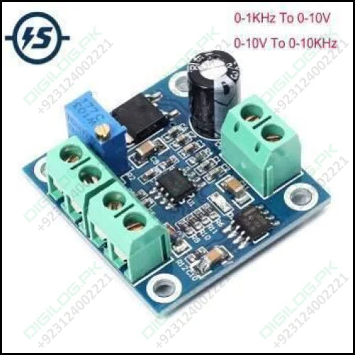
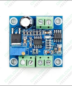
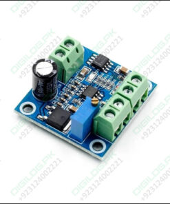
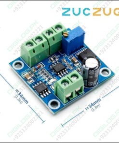
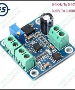
It can convert the frequency pulse signal to analog voltage signal, transform 0-1KHz frequency signal into 0-10V voltage output. Adjusting frequency can change output voltage, can be applied to interface conversion between PLC and frequency converter or interface matching control occasions like motion control card and frequency converter, etc . Adjusting potentiometer can calibrate the relationships between frequency and voltage. Signal input port adopts optocoupler isolation, which guarantees good anti-interference ability. F/V converter module, response time is around 0.3-0.5s. If the frequency is adjusted at one time by a large margin, a certain response time is required.
Specification Of Frequency to Voltage Converter :
- – Operating voltage: 13.5V-30V
- – Input frequency range: 0-1KHZ
- – Output voltage range: 0-10V
- – Instructions for use
- – VCC: Operating power supply
- – GND: Power ground
- – F: A input frequency pulse signal
- – GND: input ground
- – VOUT: output corresponding voltage
- – GND: Output ground; Common ground for modules
- – Connect the operating voltage to VCC and GND. Do not reverse it to avoid damaging the board and the device.
- – Connect the frequency pulse signal to F and there is a corresponding voltage output at VOUT.
- – Input and output corresponding relationship: 100HZ=1V, 1KHZ=10V.
- – If there is a deviation in the correspondence between the use, adjust the potentiometer on the board to calibrate.
- – The module accuracy is 1%, and it cannot be applied to fields which has high demanding of precision.
- – Input different frequency, output will correspond to certain voltage.
- – Input pulse level can be 5V, 12V, 24V, serial resistor not needed. But if you input signal frequency, the time should be more than 0.5s
- – If you want to use it with PLC, it supports NPN. Please make sure that there is GND wire
- – If you want to use it with encoder, it requires constant rotation of the encoder for more than 0.5s


Be the first to review “Frequency To Voltage Converter Module 0-1khz To 0-10v Digital To Analog Voltage Signal Conversion Module” Cancel reply
Related products
Industrial Components
10k Ntc Thermistor Thermal Resistor Temperature Sensor Ntc-mf52at
Arduino Modules Components
10kg Range Weighing Sensor Load Cell Sensor For Electronic Yzc-131
Battery & Cells
Solar Charge Controller12v 24v 20a (cs2024z) In Lahore Pakistan
Arduino Modules Components
Industrial Components
Arduino Modules Components










Reviews
There are no reviews yet.