Lm7815 Voltage Regulator
₨ 45

We all very well know regarding the building procedures a DC power supply circuit using a transformer, a bridge rectifier and a filter capacitor.
It just requires connecting four diodes in a bridge configuration and connect it to the secondary of the transformer, the capacitor goes to the output of the bridge terminals.
The output produced across the capacitor is approximately equal to the rated voltage of the transformer, rather a few volts higher than the transformer spec.
However the voltage obtained from the above simple configuration is never regulated and stabilized, meaning the output from it will never be constant and will vary with the varying input mains voltage levels, which we know is never constant.
A varying voltage can cause drastic consequences to a sensitive electronic circuit, for example a TTL, LS and HC series of ICs cannot tolerate more than 5 volts and can get immediately damaged.
A CMOS IC cannot stand more than 16 to 18 volts.
A relay if operated at voltages more than its rating can become hot and waste electricity unnecessarily.
There are several other issues which might be faced with electronic circuits if the applied is an unregulated one.
For solving the above issue, many high grade yet very simple to configure chips have been designed and are available cheaply and plentifully in our electronic markets.
The 78XX voltage regulator series for example, comes with most of the standard voltage ratings which can be used in conjunction with an ordinary power supply DC for obtaining high grade, clean voltage controlled outputs.
The specifications of the 78XX series IC can be understood with the following points:
Output voltage tolerances are around 2% at Tj
= 25 C and 4%
Line regulation is around 0.01% of VOUT/V of VIN at 1A load
Internal circuitry is thermal and overload protected
Internal short-circuit current limit protections are also included
Output transistor safe area protection is also one of the features of these ICs
The entire range of these ICs are given in the following table:
How a 7805/7812/7815/7824 ICs are used or connected in electronic circuits.
A classic example can be seen in this article where a 7805 IC is used as a cell phone charger regulator.
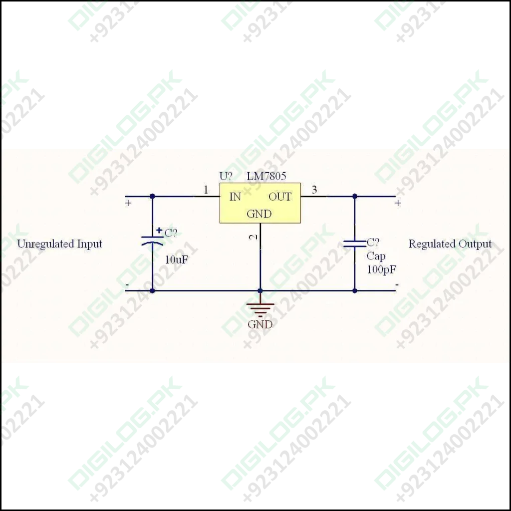
Refer circuit diagram
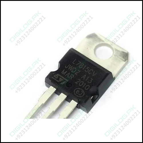
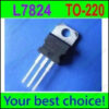
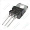
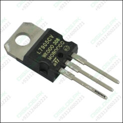
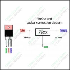
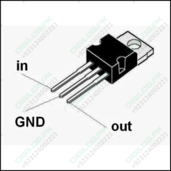
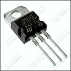
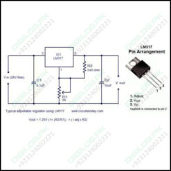
- These ICs have just three leads, making it very easy to understand and connect. The leads are assigned as input, ground and output respectively.
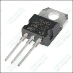
- Keeping the printed side toward you, the left side lead is the input, the center one is the ground and the right side lead is the output.
- The DC from any standard power supply is applied across the input and the ground leads of the IC, the positive goes to the input while the negative is connected to the ground.
- The output is acquired across the output and the ground pins of the IC, the positive being received from the “output” pin and the negative from the common ground line.
Many example application circuits and connection details can be found in this ARTICLE
Be the first to review “Lm7815 Voltage Regulator” Cancel reply
Related products
Semiconductor Components & ICs




Reviews
There are no reviews yet.